Built withPython · Shapely · OpenCASCADE · Claude Code
StatusIn progress
SourcePrivate
Why
RC v1 showed how much saving weight matters. The other methods tried between RC v1 and RC v2 to save weight are covered here. This page goes into detail about printing in PLA Aero (LW-PLA) instead of regular PLA.
What makes LW-PLA so light is also what makes it difficult to work with. LW-PLA foams as it leaves the nozzle, so even after the extruder stops it will still ooze. Retraction does not solve this, so every travel move of the print head strings. Furthermore, a change in print speed also changes the density of the part.
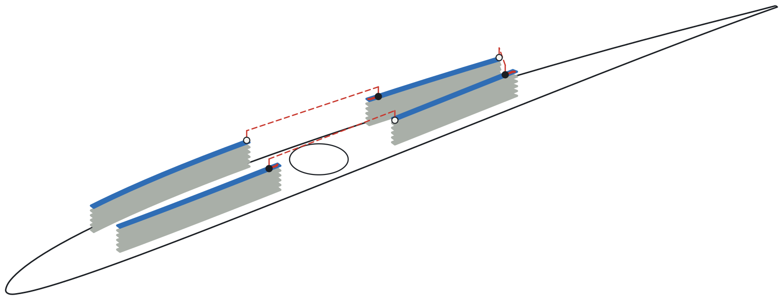
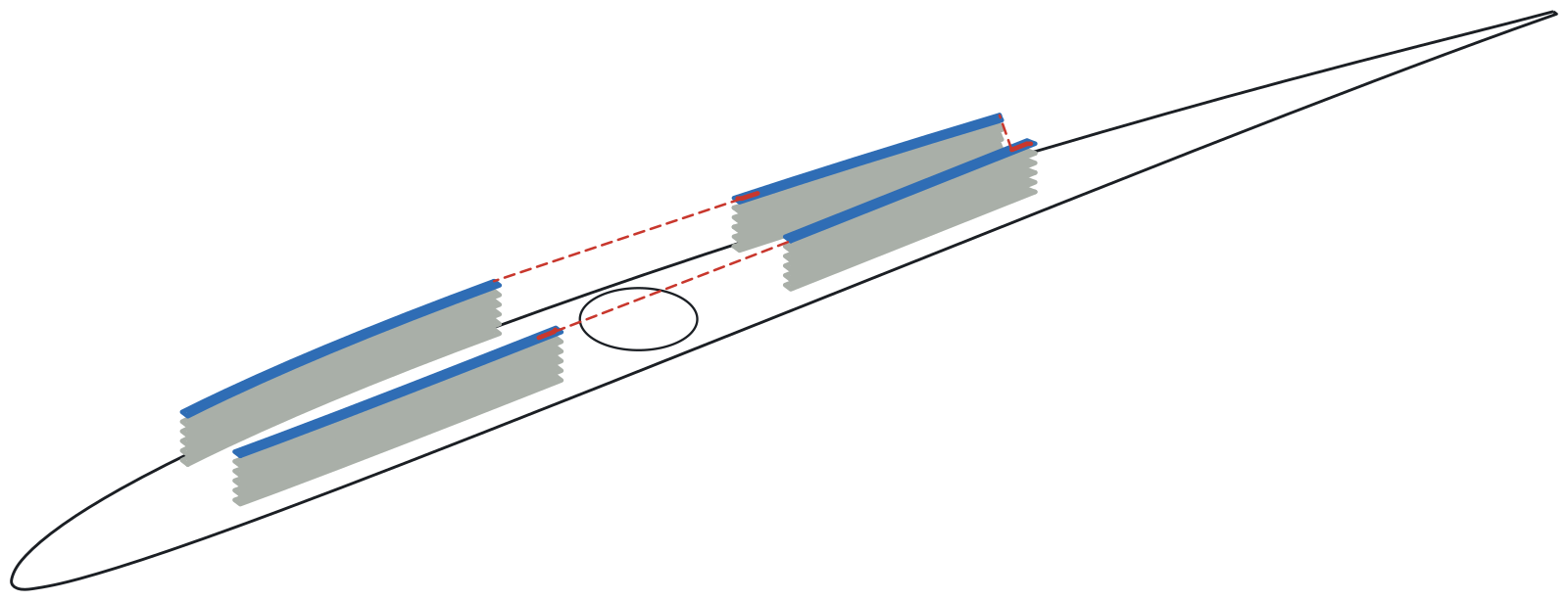
Bambu Studio and other slicers are not designed specifically for this oozing behaviour of LW-PLA, so their prints usually come out strung on the inside. The root face shows this issue: Bambu Studio’s default solid bottom has 47 travel moves on the bottom layer alone.
Bambu StudioThe root face’s first layer as Bambu Studio’s default solid bottom lays it with dashed lines representing travel (brim not shown).Plane SlicerThe same layer from the Plane Slicer: the skin, a wall round each opening and rings of fill, printed as one path with no travel
Bambu Studio (and many common slicers) support spiral vase mode, which helps with this issue. Vase mode prints continuously and prints each layer as one wall, thus never travelling. But it is very limited since it can only print one outline. This forces you to design your part in a very specific way in CAD, and limits the shapes and features the part can have.
This is why I began working on a custom slicer. This slicer reads a plain solid wing segment from SolidWorks and generates the internal gridding itself in such a way that we can still achieve the continuous prints of vase mode. But this slicer is much more flexible than vase mode. Because it builds the structure itself, it can close the root and tip faces with solid layers, keep a spar bore and tab pockets open through them, print around a slot cut through the skin, and print the joining tabs in a second filament, all from a plain solid in CAD.
ImageThe RC v2 tip segment as the slicer builds it.
The Lattice
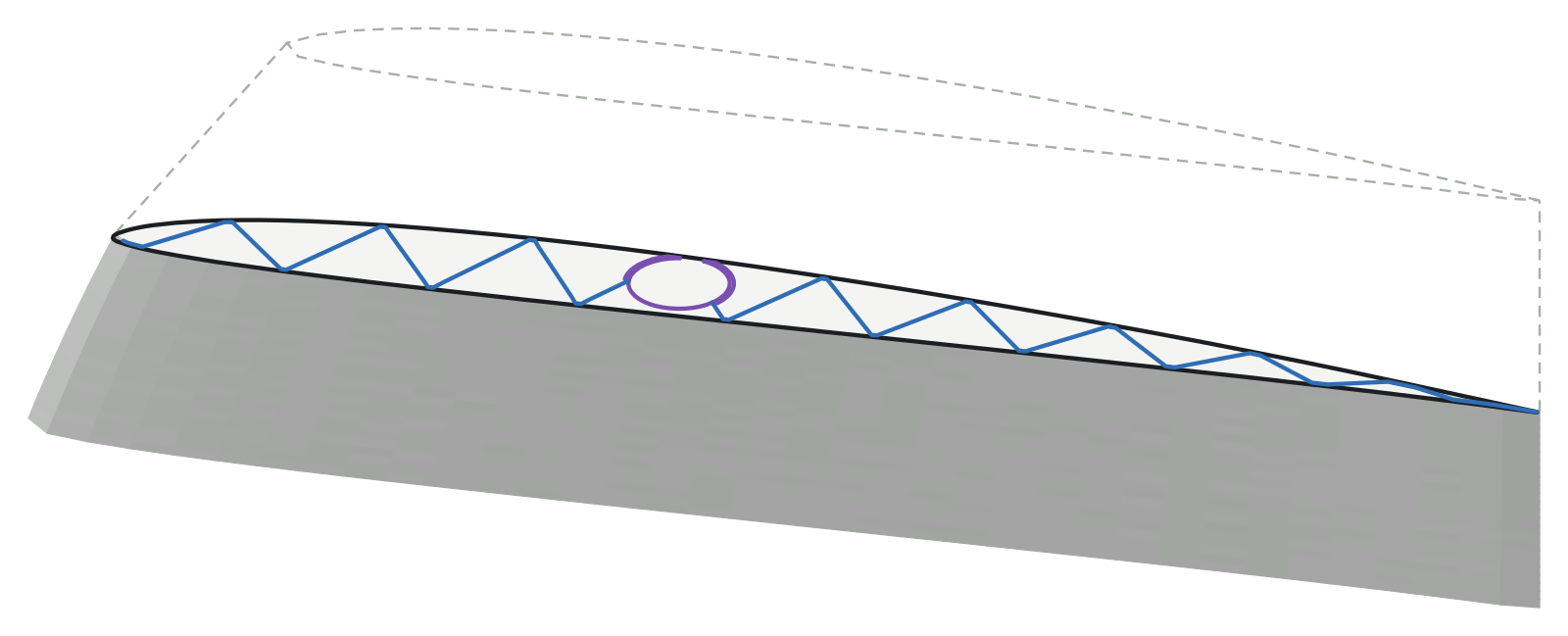
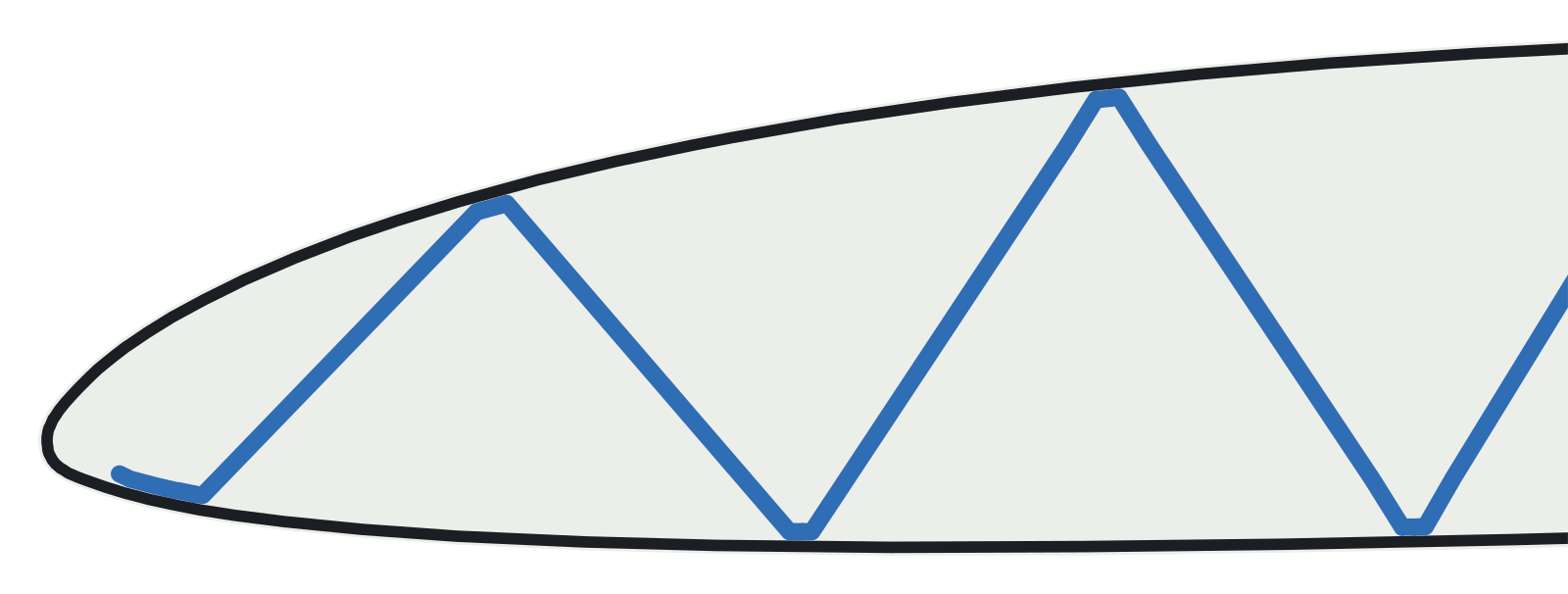
The lattice work began with a standard 45° V or X-shaped grid inside the wing. Wherever the grid meets the skin, two diagonals meet in a V. With the skin on either side, that makes four lines at every one of those points, so the nozzle can come in on one line and leave on another, and print the whole layer as one path without lifting off.
ImageOne layer’s zigzag at the wave’s crest (blue), and 12.6 mm further up the span at its trough (grey).
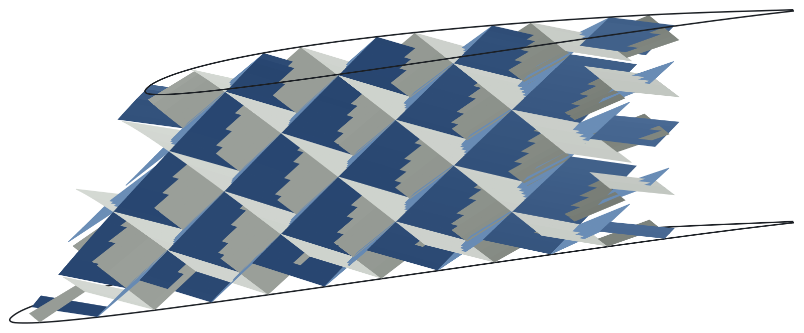
The first pattern was a double lattice (creating the standard X grids used with PLA) created through combining two zigzags. But the two zigzags also cut through each other at mid-depth, about nine times a layer, and every crossing will mean the nozzle prints over plastic that was already laid.
ImageThe double lattice (one grey, the other blue) on the same segment, skin removed, root at the bottom.
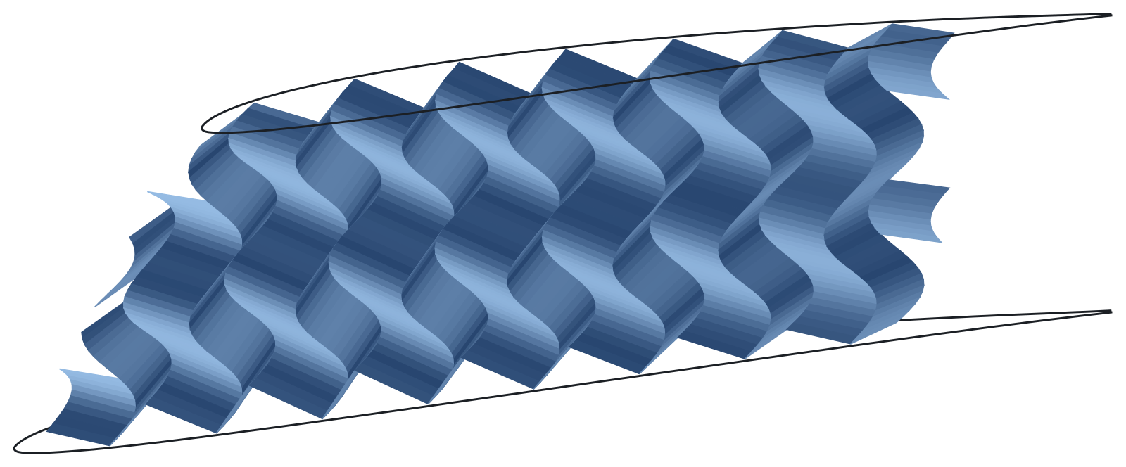
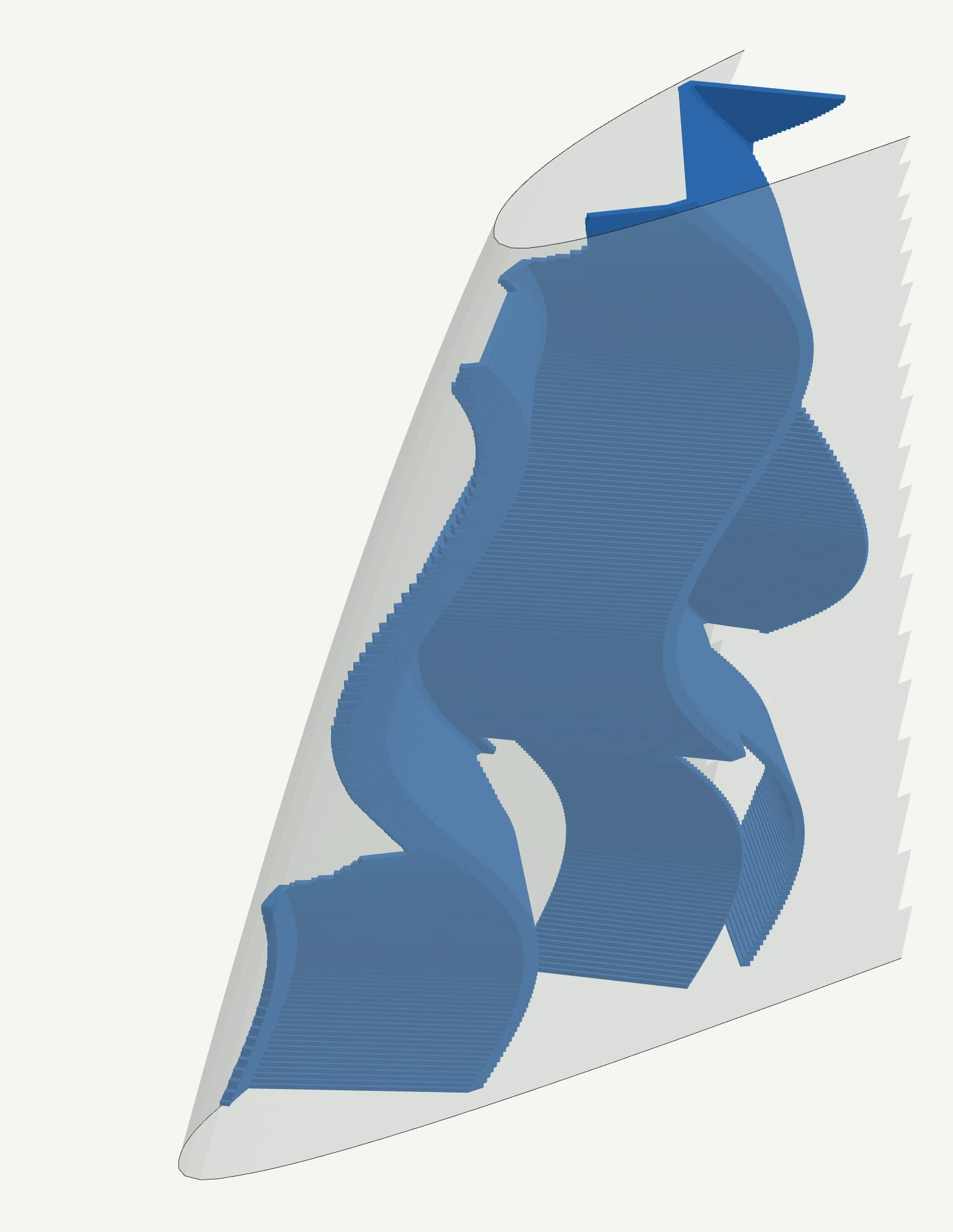
What I tried next, and ended up using, is a single zigzag with a phase wave: one V-shaped grid that slides back and forth along the chord as it goes up the span. It only ever meets itself at the skin, so its walls never cross. And because it keeps sliding, the points where it touches the skin don’t stay in fixed spots: they sweep along the chord, evenly spaced on every layer.
ImageThe walls the zigzag builds up the 50 mm segment, skin removed, root at the bottom.
Compared with the X grid on the same segment, the wave uses 14% less material per layer and never leaves more than 16 mm of skin unsupported, where the X grid leaves up to 24 mm, so the skin is better supported against denting and buckling. What it gives up is shear: about a quarter less between the skins and a third less along the chord. The table below compares the two; its numbers are measures of the geometry, not a stress analysis.
X grid
Wave
Material per layer, skin and lattice
1.00
0.86
Shear between the skins
1.00
0.74
… per mm of lattice
1.00
1.03
Crush stiffness
1.00
1.06
… per mm of lattice
1.00
1.48
Shear along the chord
1.00
0.66
Longest bare skin, worst layer
24 mm
16 mm
Crossings per layer
8.9
0
TableThe wave (8 mm pitch) against the X grid (12 mm pitch) on the tip segment, averaged over 250 layers at three spans, with the X grid as 1.00. The better of each pair is highlighted.
Holes
Printed wings often have holes cut through their internal grid to save weight. But we cannot use an ordinary hole with this slicer because it leaves two dead ends on every layer that can only be reached by travelling.
ImageA sketch on the 6 mm layer: a 4 mm round hole through one wall (dashed) cuts its diagonal and leaves two dead ends (red).
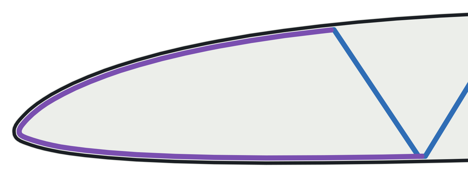
A shelf hole (refer to below image) does work. Two of the V’s that reach the lower skin are left out, and a shelf line runs across where their tips were, so every point still has an even number of lines and the layer stays one path.
ImageOne layer 9 mm into a shelf hole: the zigzag (blue) and the shelves (purple).
However, the shelf hole is not efficient. It takes out the deepest walls, in the middle of the chord, which carry the shear between the skins: 23% less of it. And I found that spacing the zigzag out from 6 mm to 8 mm saves more weight for the same amount of shear lost, and leaves the skin better supported. So the holes were dropped.
Weight
Shear between the skins
Longest bare skin
6 mm pitch
5.78 g
1.00
12 mm
6 mm, two 40 mm holes
5.52 g
0.77
36 mm
8 mm pitch, no holes
5.42 g
0.77
16 mm
TableThe tip segment’s skin and lattice at 0.5 g/cm³, the shear relative to the 6 mm lattice. The best in each column is highlighted.
The Top Cap
One issue with vase mode is also it leaves the top cap open, which is not ideal when you want to join two wing sections together. Therefore it is one of the requirements of this slicer to be able to produce a closed top cap while still printing in a continuous path.
When doing the top cap, the first layer of the cap has to bridge over the lattice, and LW-PLA is weak at bridging. Therefore something needs to be done to the lattice to reduce the amount the cap needs to bridge.
The first method tried looks like the following. It works, but every line ends in a sharp turn (sharp change in directions is not ideal for LW-PLA).
ImageMethod 1: the diagonals bent to run along mid-depth, with red representing where a cap bead is laid over air.
The fix was to fold the diagonals instead. Over the last few layers under the cap, each one folds into a Z between its two nodes, creating this sinusoidal type shape on each layer. This allows the cap’s first layer to be a spiral running along the chord, bridging roughly half as far.
Interactive · the layers through the fold and the cap
InteractiveThe top cap printed over the sinusoidal like lattice.
Bend
Fold
Cap’s first layer over air, median
3.6 mm
1.6 mm
… worst
7.4 mm
4.0 mm
Sharp turns on the cap’s first layer
295
27
Open through two or more cap layers
1.85 mm²
0.02 mm²
Segment weight
7.49 g
7.66 g
TableThe two ways under the cap, measured on 10 Oct on the tip segment, weight at 0.5 g/cm³. The better of each pair is highlighted.
The other three cap layers are the same spiral, walked in, out and in again, so each layer starts where the last one ended. Against Bambu-style lines at ±45° laid as one path, the spiral covered more of the face (99.8% against 98.8%) with 28 sharp turns a layer instead of 208.
Bambu-styleLines at +45° on the cap’s second layer, joined end to end into one path. Sharp turns are represented by dots.SpiralThe spiral on the same layer: its rings turn sharply only at the nose and where they run out along the middle. Sharp turns are represented by dots
Initial Testing
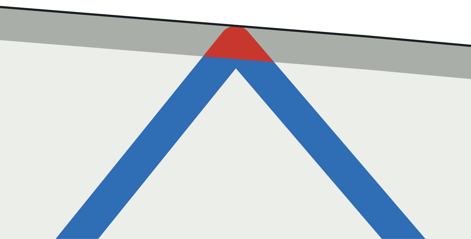
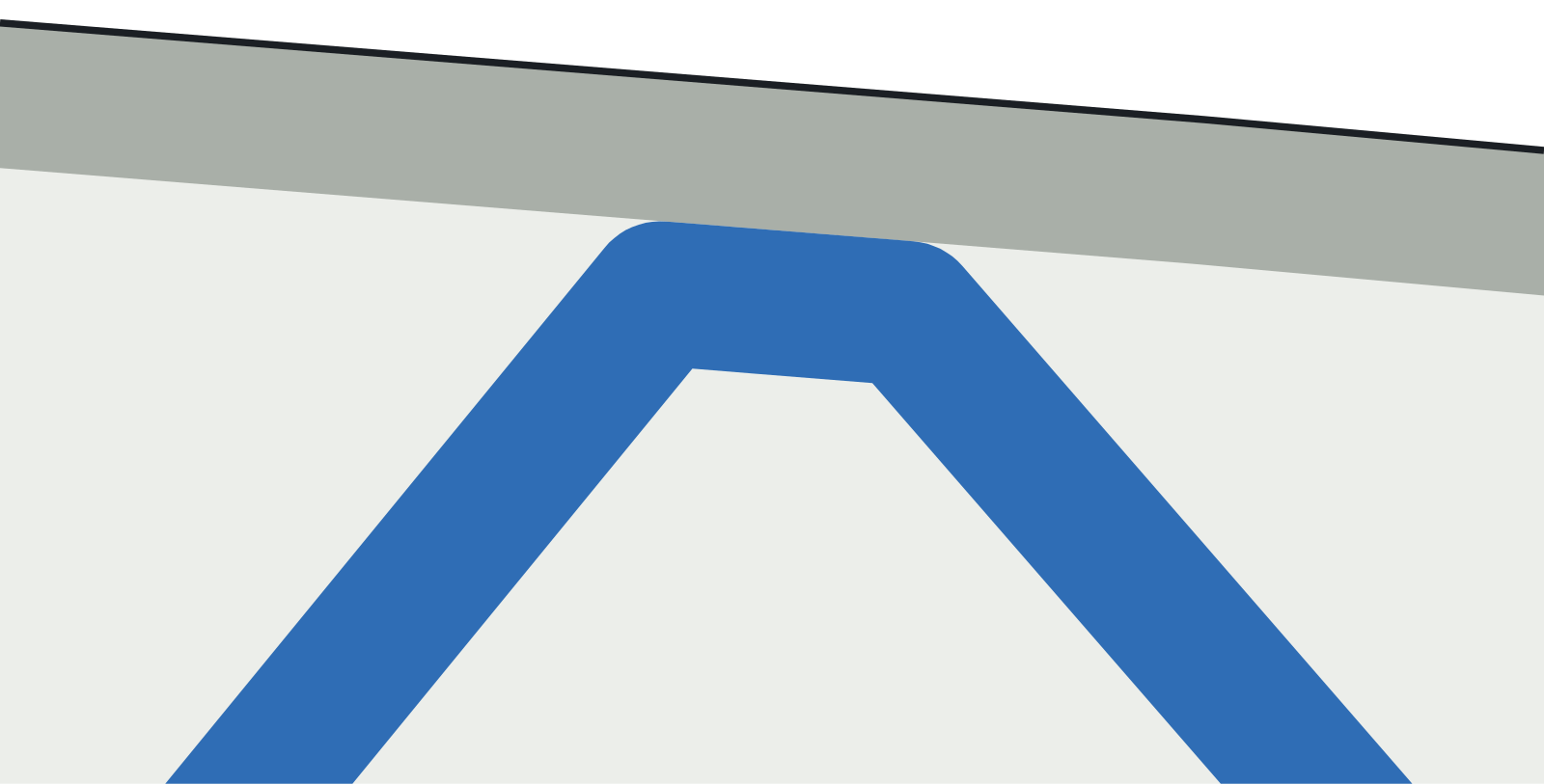
The first test prints showed the gridding through the skin in both PLA Basic and LW-PLA tests. Essentially the issue was every diagonal on the V shaped grid ended on the skin’s centreline, so the bead is pushed through the outer skin surface. This was made even worse once LW-PLA was used (due to foaming). Now every lattice line stops on a line just inside the skin, and a tunable setting, skin_overlap, sets how far its bead may reach into the skin’s. For LW-PLA that is measured on the swollen beads, so the foam can’t push it back through.
BeforeThe first print: two diagonals meeting the upper skin.AfterThe 15 Oct baseline, the same place: the lattice stops on a line inside the skin.
The LW-PLA test prints on 13 Oct also exposed another issue. The tab pockets meant for joining wing sections together came out too narrow for the tabs (when they were fine on regular PLA). This was because the foamed beads swelled past their nominal width.
So the swell is now a setting of the filament, tuned like a line width: two offsets, each in mm a side. hole_compensation grows every void before anything is laid round it, and contour_compensation shrinks the outer surface.
The Nose
Up until this point, there were no specific treatments for the leading (nose) and trailing edge. The zigzag can’t reach all the way into the nose, so it stops where the skins are under 2 mm apart. So the skin right around the leading edge was unsupported.
It was worse than bare skin. The zigzag slides with the wave, so the node at its front end changes from layer to layer, and a new front end can only grow forward as far as the layer below holds it. Up the span the front of the lattice wandered from 0.6 mm to almost 9 mm behind the leading edge, leaving a ragged edge of short walls and spurs inside the nose.
BeforeThe front edge wanders up the span near the nose.AfterDoubled nose skin.
Five ways of closing the nose were sketched. A doubled nose was chosen. The zigzag’s front end is fixed at one node for the whole wing segment and a second bead doubles the leading edge of the wing.
BeforeThe zigzags stop short of the nose.AfterThe doubled nose skin.
The Tabs
Some wings join their segments with tabs printed standing on the tip face. The issue with the tabs is that they are separate parts/strips, so it is impossible to print them in one path. Test prints were done on LW-PLA to compare two types of travel moves. First a wipe back over the last bead with a retract and a 0.4 mm lift, and the second being just a wipe alone. Both of these were not great and had a lot of stringing (LW-PLA oozes on every travel).
ImageWipe, retract and lift on a set of tabs, heights ×5.ImageWipe alone on a set of tabs.
Next, I tried using a single material swap at the first tab layer to print the tabs out of regular PLA (which barely oozes). And this works well at the cost of more weight (although the strength of these tabs are vital, so its not completely wasted weight).
Horizontal Slots
A wing in practice is almost never a perfect outer skin. Very often slots need to be cut through the skin perpendicular to the span to attach other elements to the wing. This was something that vase mode completely fails at since these slots require a cap surface to be printed in a local section.
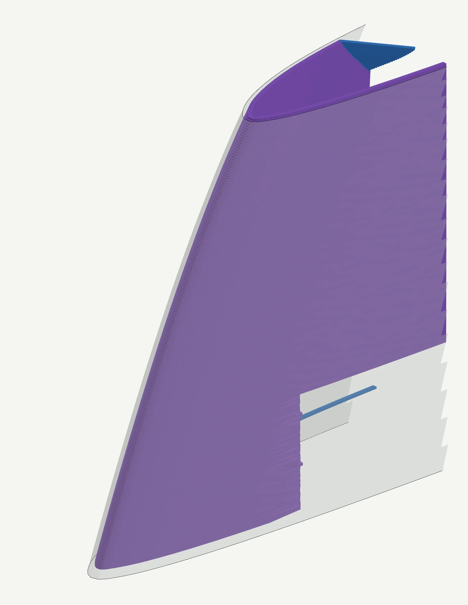
To achieve this, the lattice never moves to fit an outline, and where a lattice line would cross a designed slot, it stops at its wall. The cut ends are joined by shelves along the wall, so the layer is still one path.
BeforeOne layer of a test wing, diagonals drop straight across the slot, and the doubled nose skin (purple) runs round it.AfterThe lattice no longer crosses the slot.
A slot that runs square to the print bed (in the X-Y plane) would have a flat roof and floor (localized caps). The roof’s bottom layer is laid over air above the empty slot while the floor’s first layer is laid over open lattice. The slicer now closes each with solid layers over the slot’s footprint spliced into the layer’s walk to maintain the single continuous path.
Interactive · the slot’s floor, its layers and its roof
InteractiveHow the slicer prints the roof of a slot.
Next
A foam table. How wide PLA Aero’s bead prints, and how dense it is, changes with nozzle temperature and flow. Because the fits need to be precise, it is important to understand how LW-PLA behaves and swells at different flow and temperature.
Separate profiles. An example of this is where the aileron starts, the section will have one layer at full profile while the next one is smaller with the aileron cut out of it. Therefore the slicer must close what the smaller layer no longer covers with a local top cap (similar to the slot’s roof).
Weight. More weight-saving experiments, to bring the wing’s weight lower still.