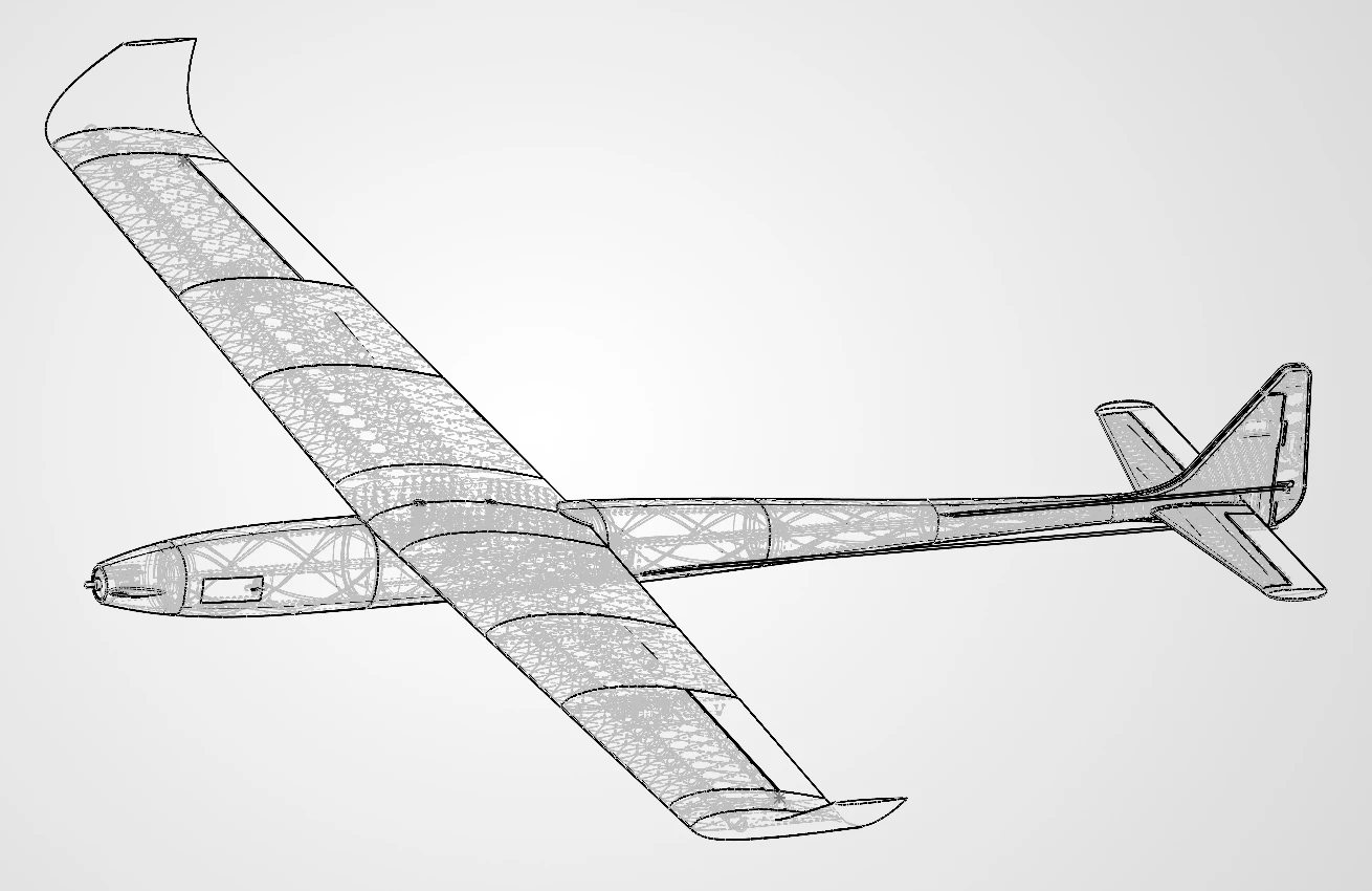
A 1.6 m fixed-wing aircraft designed in SolidWorks and 3D-printed. It was abandoned in favour of RC v2 when the printed parts proved too heavy and showed print-quality problems.
Before v1, I had designed model aircraft such as the MiG-17 and the Bf 109. v1 tested the same skills, surface modelling, lofting and parametric design, on an aircraft designed from the start to be manufactured and flown, where every surface also had to print, fit together and carry a load. The goal was simply to get it in the air, with no endurance, speed or payload target to meet.
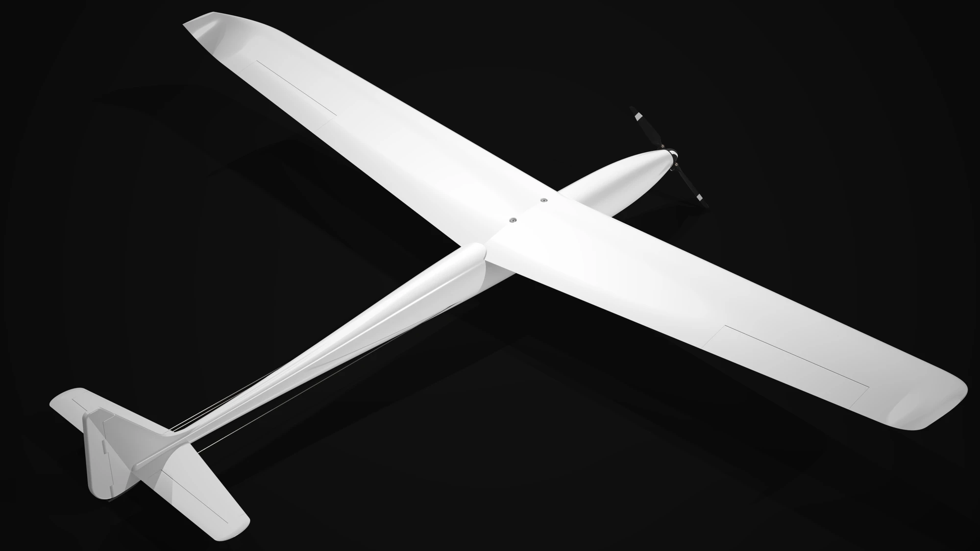
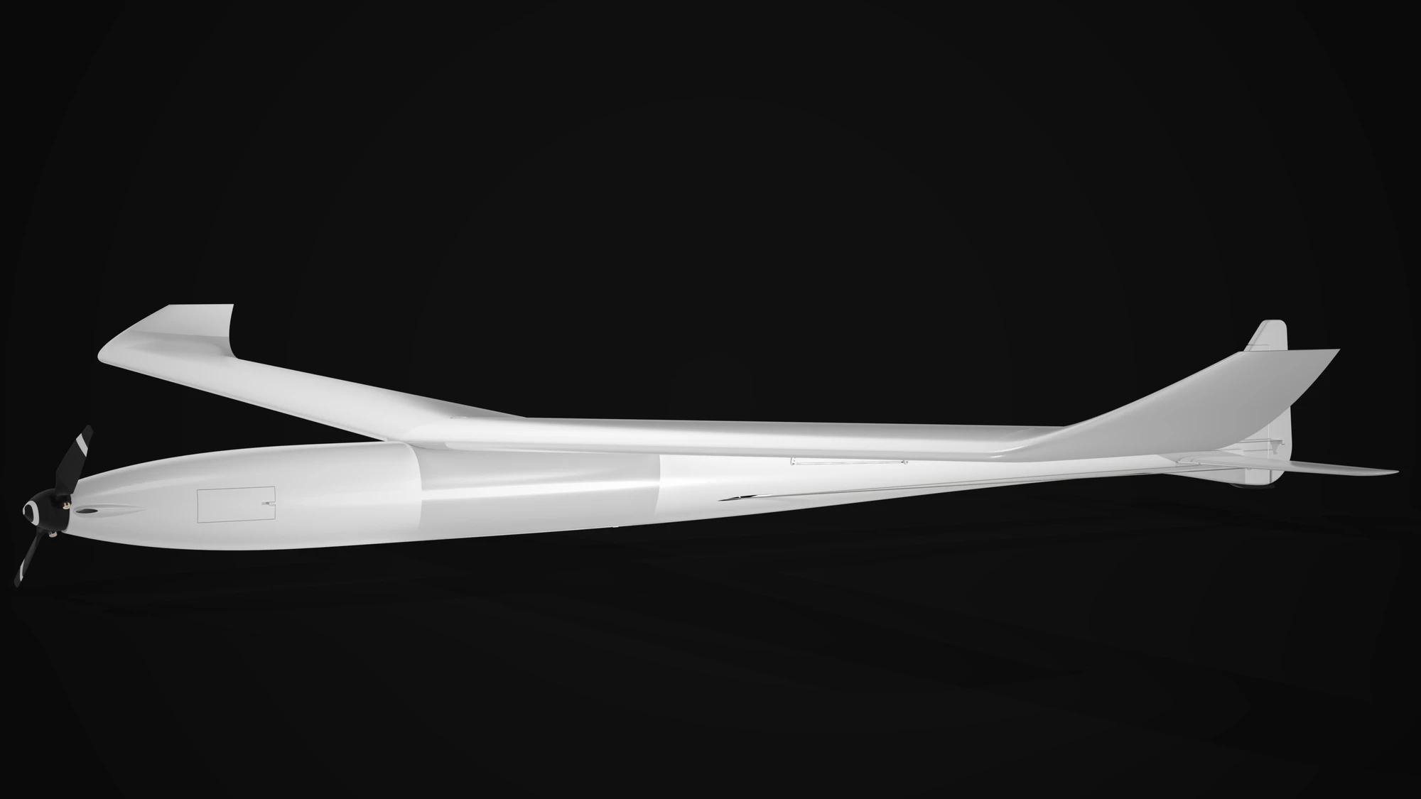
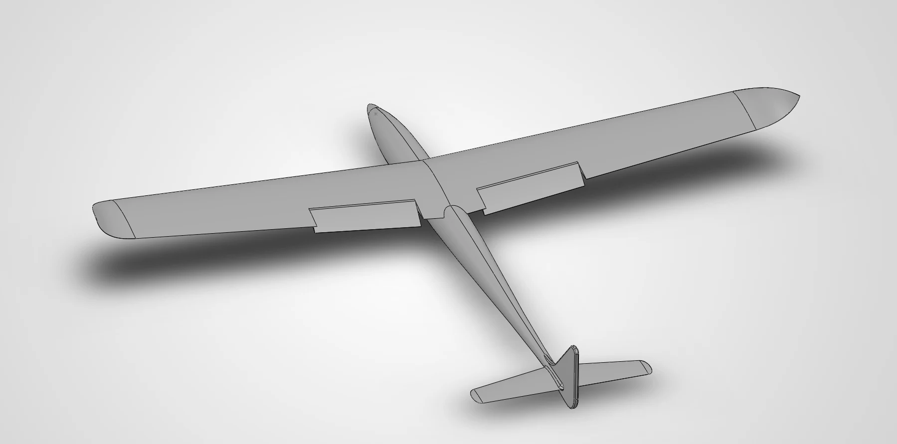
Renderv1 as designed, from above and aheadRenderThe same aircraft from low and ahead
Concept
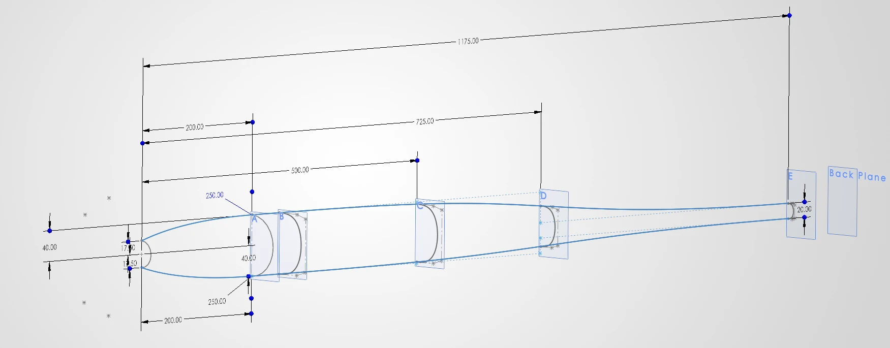
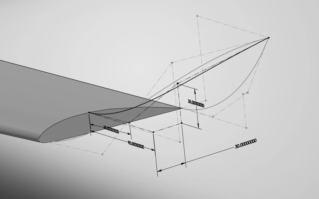
The fuselage began as a side profile and a set of cross-sections, and was lofted into one body along guide curves. I then designed the wing on a Clark Y section, chosen by a teammate, followed by the tail: a vertical fin and horizontal stabilisers on a NACA 0009. The team supplied models of the motor, propeller and nosecone, and a rough winglet shape, which I designed properly and lofted onto the wing tip.
SketchThe fuselage as a profile and five dimensioned stations, A to E, with the curves it was lofted along
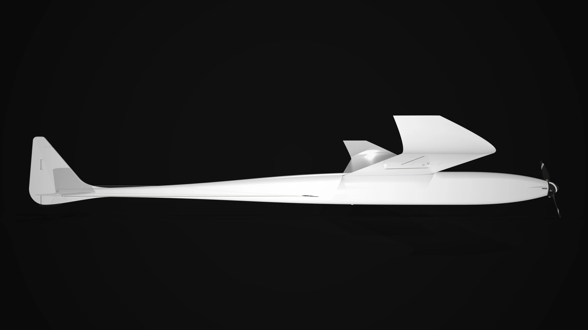
RenderThe final fuselage, seen from the sideCADThe assembly used for CFD, with flaps down
A first pass at CFD
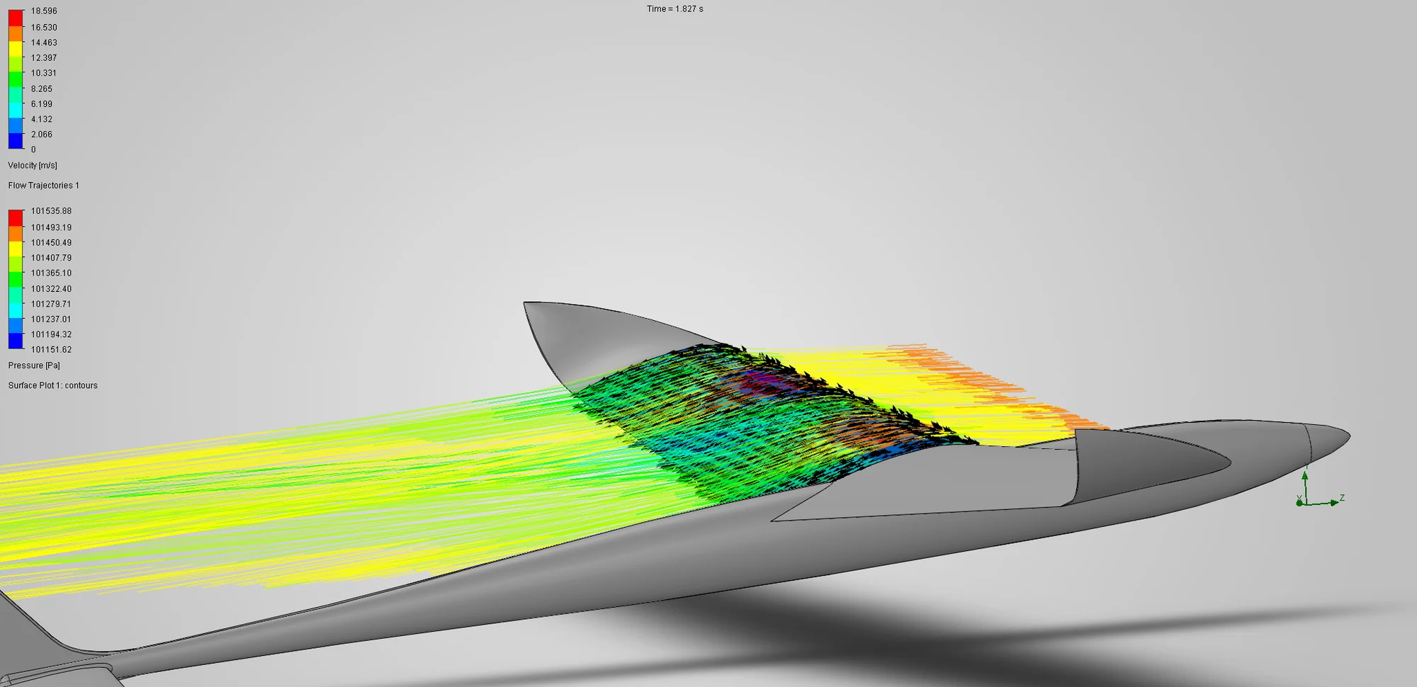
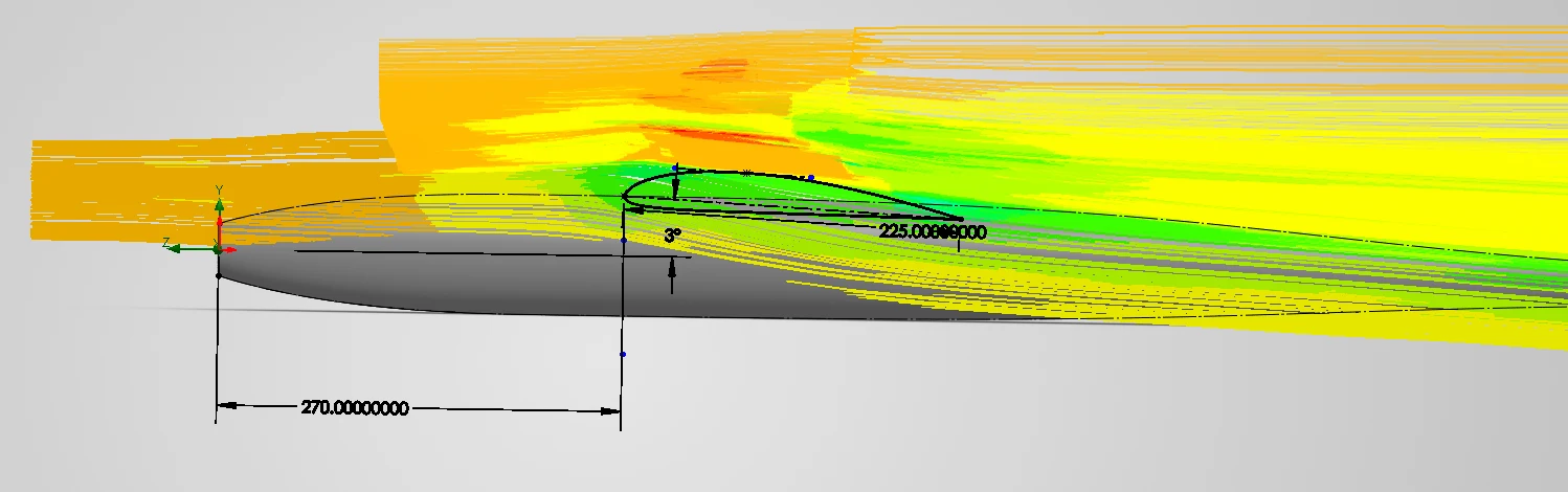
v1 was my first use of SolidWorks Flow Simulation, and I kept it deliberately basic. I mostly used the default settings, only changing automatic mesh fineness on some runs. From each run I read three results: lift, drag, and the pitching moment as a rough check on balance. Between runs I adjusted the wing’s chord lengths, leading-edge position and angle of attack, aiming for the highest lift-to-drag ratio.
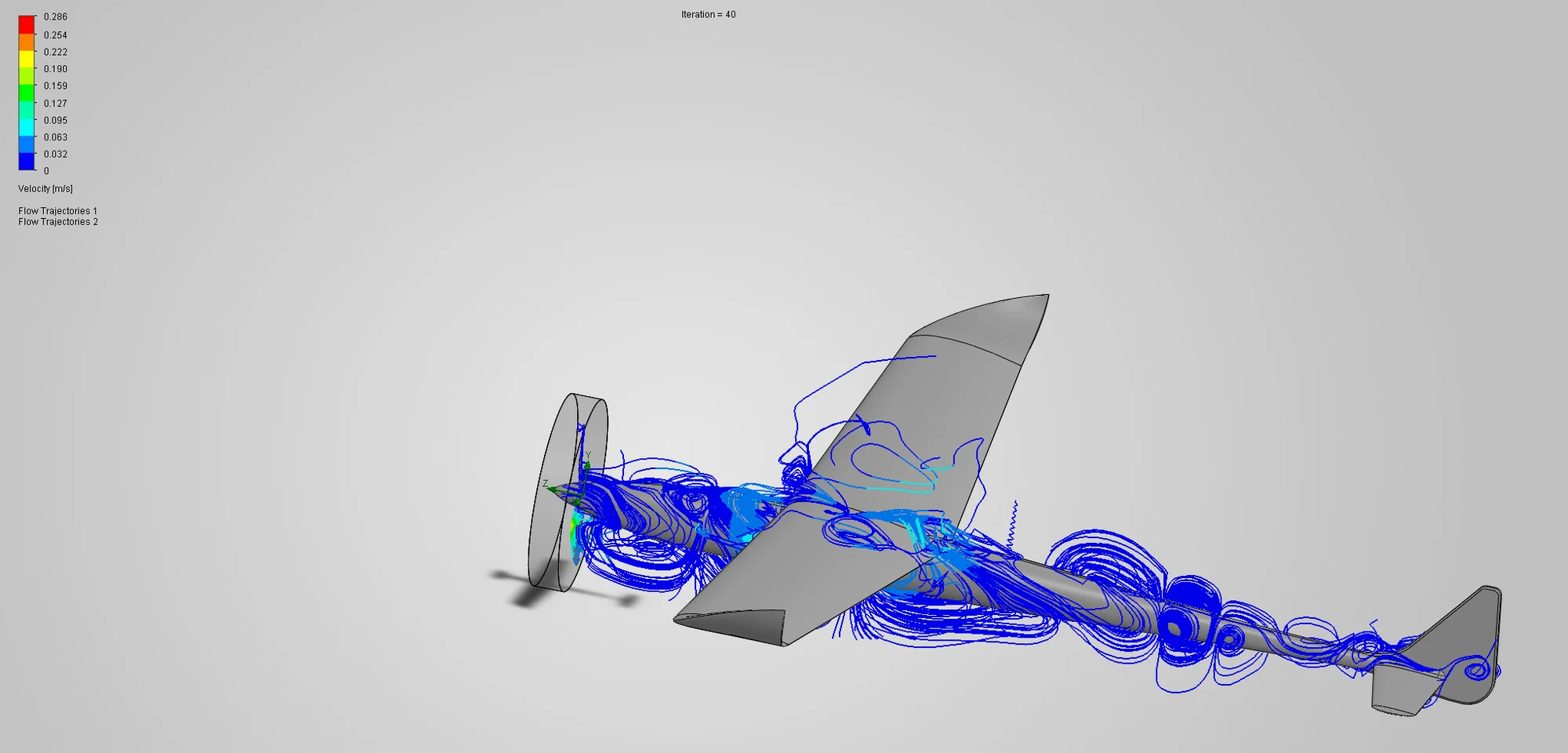
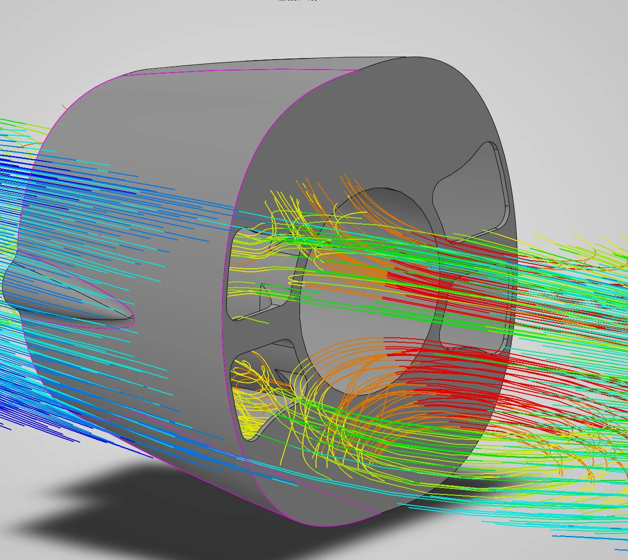
Two further studies went beyond that. One put the propeller in the flow as a rotating region, and one looked at the air taken in through the nose intakes.
CFDFlow trajectories over the wing, coloured by velocity, with pressure on the surface behind themCFDThe root section sketch over trajectories for the whole wing: chord, station and angle of attack
CFDThe propeller as a rotating region, 40 iterations inCFDAirflow through the nose intakes
The Fuselage
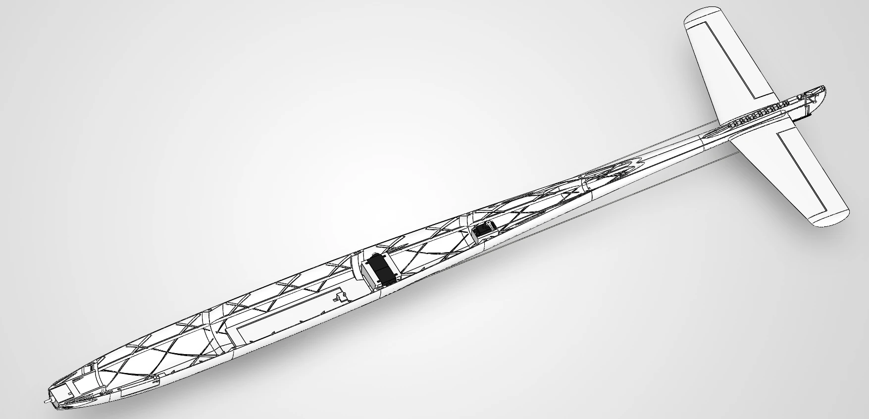
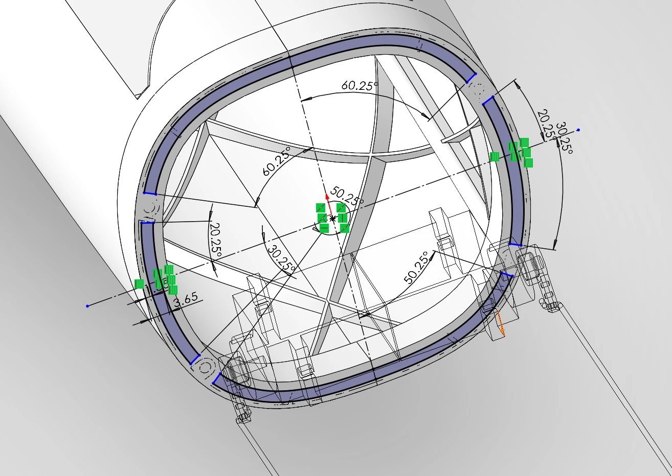
Next, I designed the details the fuselage needed to be printed. Both printers I have access to, a Bambu Lab P1S and an A1, print up to roughly 250 mm tall, so the fuselage was split into a nose and five sections. Pins join the sections together, and four steel wires, which follow the outer curve of the fuselage, guide the stack so it stays aligned. Inside, the fuselage is gridded with a helical cut pattern.
CADThe fuselage structure, the access doors and the servos, as seen through a section view on the top planeSketchSketch designing the pin for attaching sections C and D
The tail
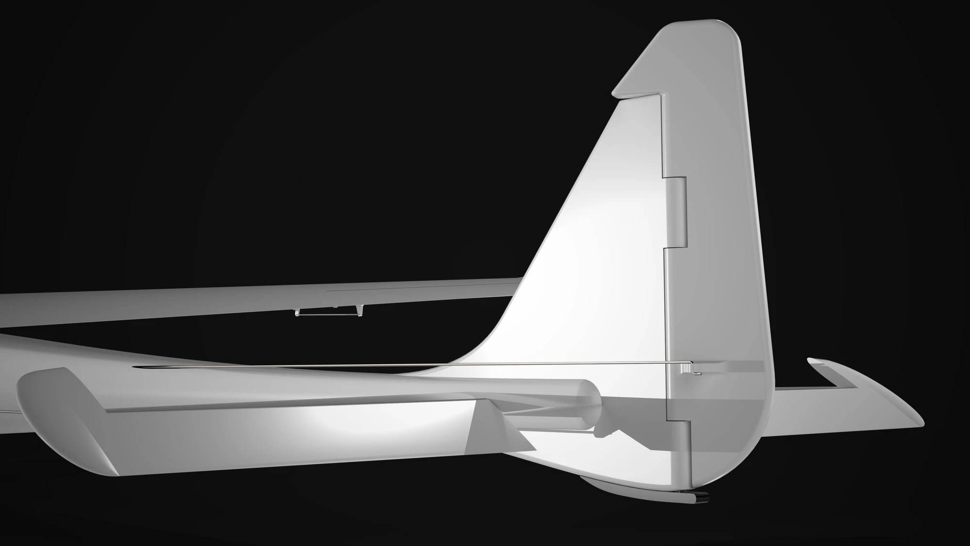
I designed the tail and horizontal stabilisers as separate printed parts. When gridding the tail, SolidWorks’ Shell would not produce a clean shell at 0.8 mm (situations like this are what the Airfoil Converter was eventually built for), so the tail settled for a 0.4 mm shell, unlike the rest of the aircraft.
The rudder and the elevators on the stabilisers are moved by 9 g servos inside the fuselage, each on its own printed bracket, through 1 mm steel pushrods that run back to the tail. The rudder turns on a 4 mm carbon rod and the elevators hang on CA hinges. A skid plate went underneath, and on 23 May the finished tail was joined to the fuselage.
RenderThe tail from outsideCADThe tail gridding and spars as seen through a cross section view
The wing
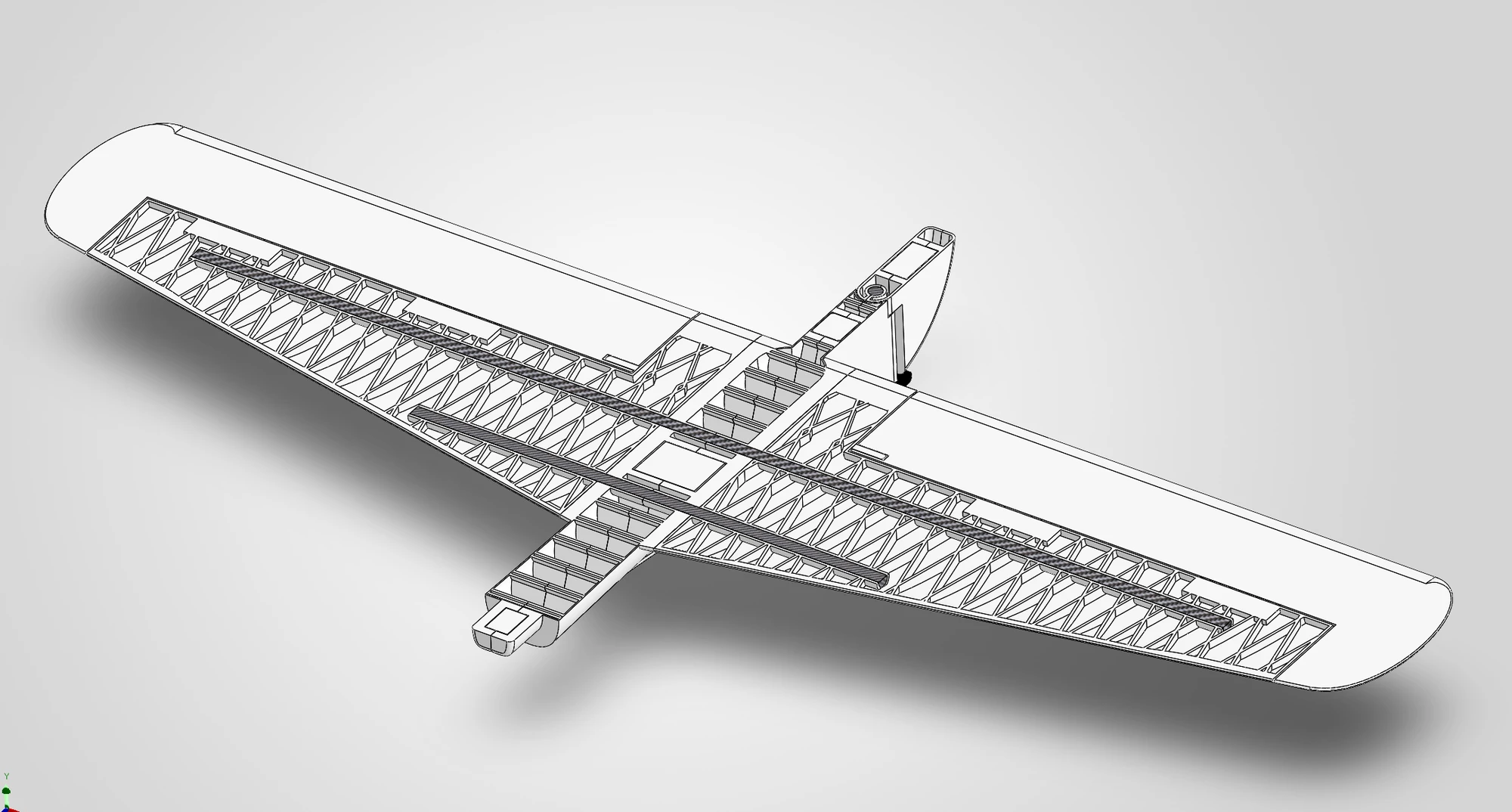
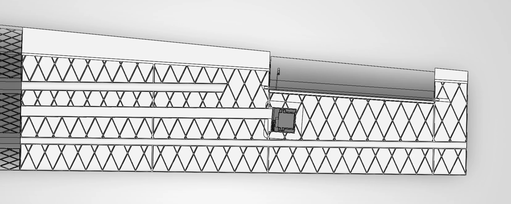
The wing, similar to the fuselage, was split into four sections of roughly 200 mm each. To maintain its structure, the wing was gridded internally and two carbon fiber spars span the wing. The wing is attached to the fuselage through a bolt at the root.
CADThe internal gridding and servo mount of the wing
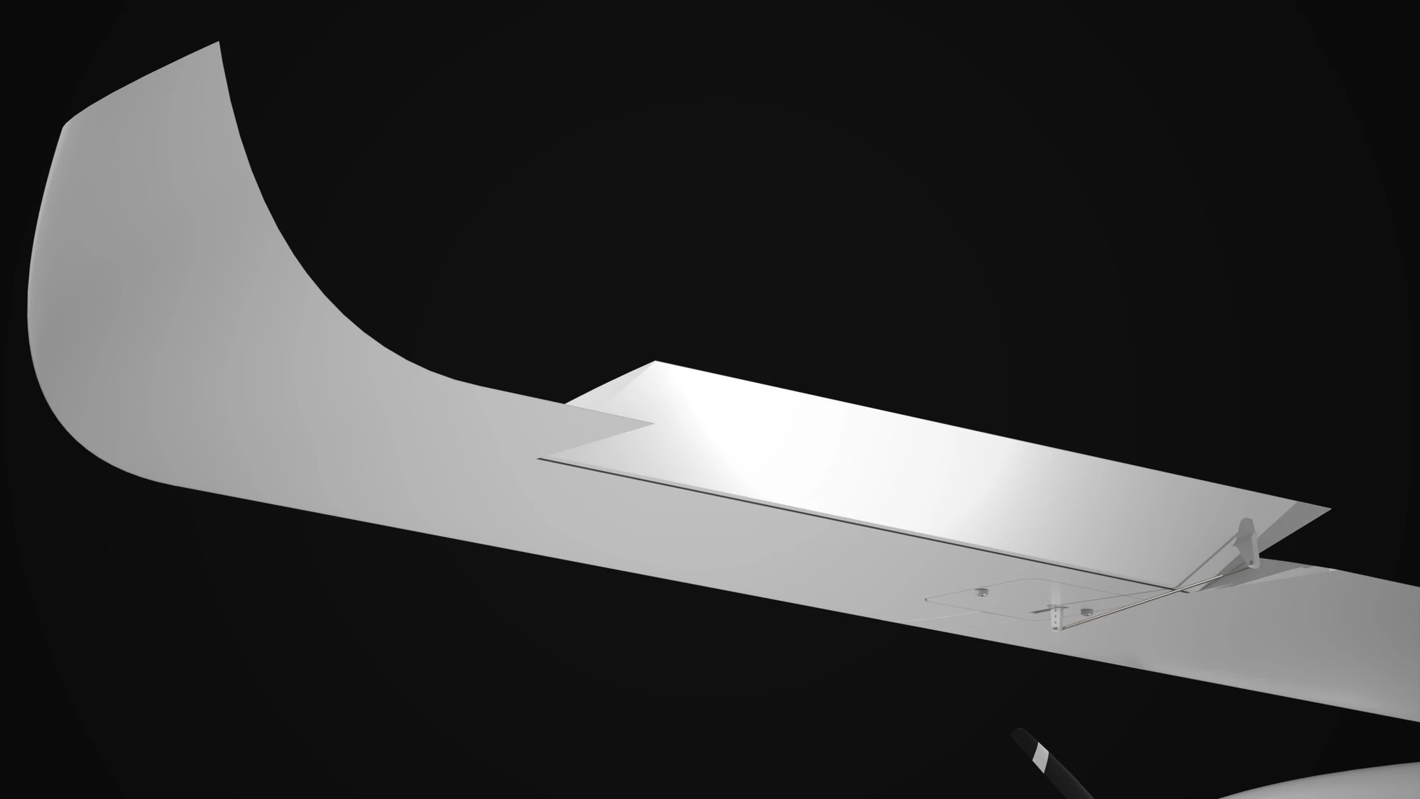
Each aileron is a separate printed part, hinged on a carbon rod and driven by a 9 g servo inside the wing. The winglet is printed as its own section and attached to the wing.
RenderThe winglet and the aileron on the wingSketchThe guide curves the winglet was lofted along, off the wing tip
Printing
By June the first parts were coming off the printer, and the aircraft went back through a second pass. This one was driven by what the prints showed rather than by what the model wanted.
The nose was redone first, to take a larger motor. Wing sections were reworked to sit together properly, and at the end of the month the tail was redrawn with a much thicker shell.
Weight
During manufacture it was becoming apparent that parts of the aircraft were going to be too heavy. The wing came out at roughly 1.3 kg, the fuselage at around 430 g and the tail close to 200 g, all on filament weight alone, without any of the electronics.
CFD results from earlier in the project gave something in the region of 9 N of lift at 11.11 m/s and 2.5° angle of attack, which would hold up a little under a kilogram, though it is not a figure I would stand behind. The printed plastic alone came to roughly twice it, with the spars, servos, motor, ESC and battery still to go in. The CFD could be well out, and the aircraft would still be too heavy.
CFDThe three goals at convergence: lift, drag and pitching moment
What it led to
On reflection, the wing is where the weight would have had to come down first. The gridding inside it is probably denser than it needs to be, and the walls and the grid are both extruded at 0.8 mm. Running that thickness in both places is close to doubling what the wing costs in plastic. Printing it in LW-PLA is the other thing worth trying.
However, neither is a setting that can simply be changed. The wing was shelled first and gridded afterwards, so the structure inside it was drawn around a 0.8 mm shell and fits nothing else; taking the walls down to 0.4 mm means redoing the grid, and that means going back to the earliest drafts of the CAD. What would be rebuilt at that point is a grid that was not efficient to begin with. The wing would have to be redesigned, not adjusted.
CADv1 in wireframe view, with the internal gridding visible
What came of that was an experiment rather than a fix. LW-PLA foams as it extrudes and strings on every retraction, so the way to get a clean surface out of it is to print without stopping, which means vase mode when printing, which in turn means a wing drawn as one unbroken shell. None of that is a material swap on the CAD that already exists. Getting a vase-mode print to come out well took a run of prototypes and a long tail of small changes. There is more on it here.
v1 was abandoned at this point, because most of its weight is embedded in the design itself rather than in anything that could be adjusted, and the wing is not the only part of it. The fuselage has little to give: it is long, and it is already using relatively little material. And the tail was not one I was happy with in any case. Its servos sit too far forward in the fuselage, a long way from the surfaces they drive, and the way it attaches to the fuselage was not well thought out and could fairly be called weak.
Although v1 never got to fly, much of what it taught went into starting a new aircraft from scratch. As a platform for learning by trying, it more than did its job.
Credits
A team of two. Herbert Zhao modelled the propeller, the nosecone, and the motor, ESC and battery that stand in for the electronics in the CAD; he supplied the rough winglet shape and fixed the tolerances on the access doors once the first ones had been printed. The Clark Y root section was a teammate’s choice. For who did what beyond that, the commit history ↗ is the record.